 Date:2023.12.22
Visits:418

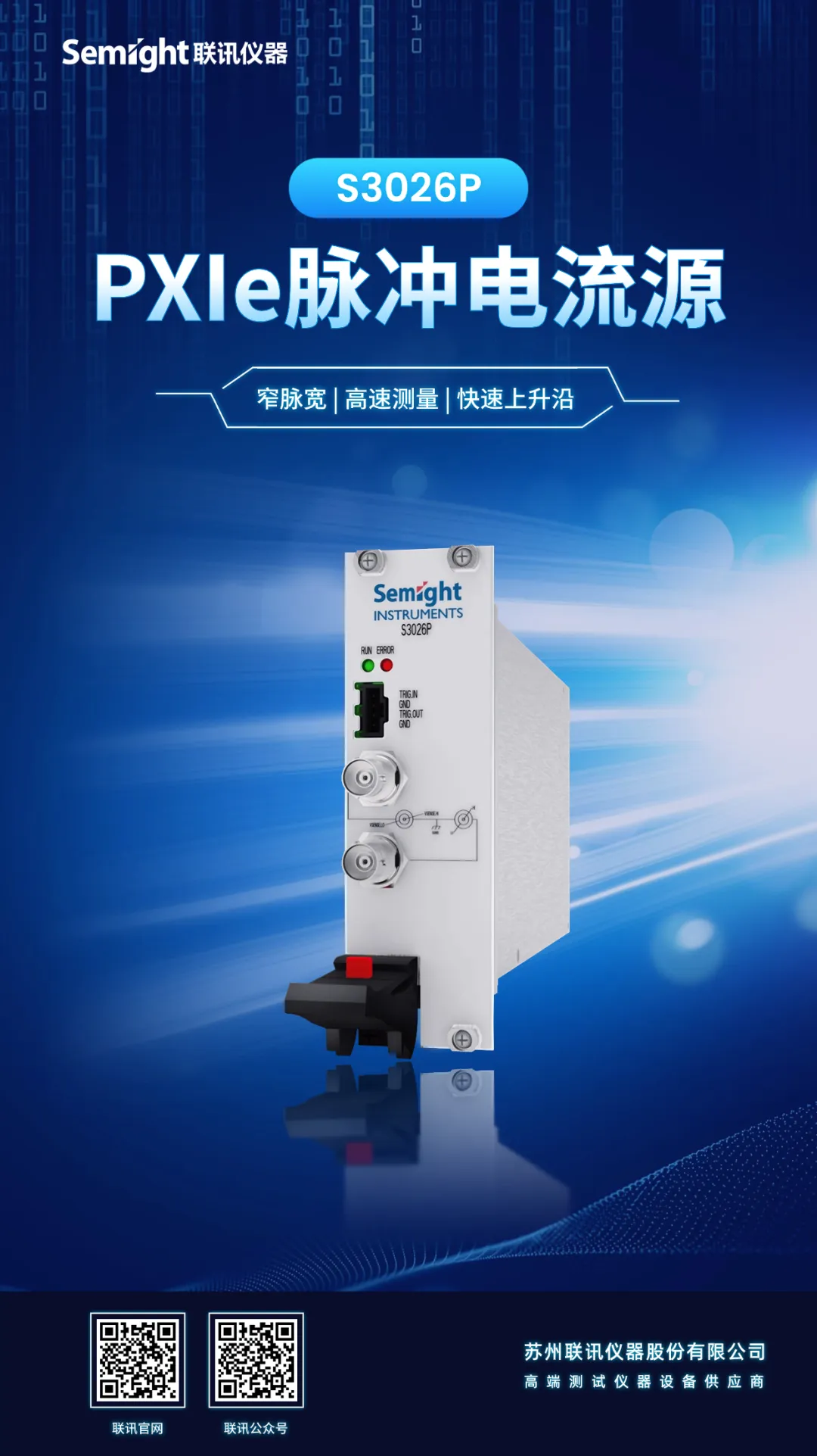
The dTOF in LIDAR Ranging uses optical pulse modulation, the narrower the optical pulse width, the higher the ranging accuracy; the higher the peak power, the longer the ranging, however, high-power lasers use DC charging with serious heating, and laser characteristics are affected deeply by the temperature, in order to measure the performance of the device in working , the need for micro-second or even nanosecond driving ability of the device to test it. S3026P Single-Channel PXIe Pulse Precision SMU supports 1us~500us narrow pulse output, and connects up to 2m cable to keep the pulse without distortion, which can be widely used in the verification test of LIDAR pulsed lasers.
1,dTOF
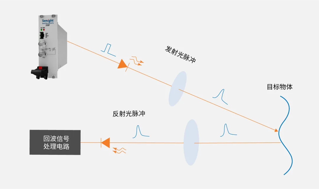
Lidar Ranging in the dTOF which is“Direct Time of Flight”, dToF uses optical pulse modulation, by transmitting light pulses to the target under test, measuring the time interval between the transmit pulse and the receive pulse, and directly calculates the distance of the target to be measured (depth information). dToF ranging, the pulse drive circuit drives the laser to emit a When dTOF ranging, the pulse driver circuit drives the laser to emit a very short duration but very high instantaneous power optical pulse, the receiving optical circuit of the ranging module receives the optical signal, which is converted into photocurrent through the optoelectronic device, and delivered to the echo signal processing circuit.

2,Single-Channel PXIe Pulse Precision SMU S3026P
Semight S3026P is a single channel PXIe pulse Precision SMU for the lidar market. It provides high precision pulse current output and synchronous measurement of pulse current and DUT voltage drop.
Product Features
01,Narrow Pulse Width
Minimum pulse width 1us, adjustable pulse width range 1us~500us
02,High Current
±1.5A pulse current
03,High-Speed Measurement
Real-time reading of pulse current and DUT voltage drop with sampling rate up to 10MSa/s
04,Fast Rising Edge
Typical rise time <200ns
Product Specification
|
Maximum load voltage |
10V |
1. Output electrical short; 2. Total cable and DUT inductance < 200nH (100k); 3. Pulse width measurement from rising edge 10% to falling edge 90% |
|
Pulse width Programming |
80ns |
|
|
Maximum pulse width Ton-max |
500us |
|
|
Minimum pulse width Ton-min |
1us |
|
|
Pulse minimum turn-off time Toff-min |
500us |
|
|
Pulse width accuracy |
100ns |
|
|
Pulse width jitter |
80ns (typical value) |
|
|
Pulse-period jitter |
500ns (typical value) |
|
|
Rise time (10%-90%) |
<200ns |
|
|
Pulse overshoot |
<0.5% |
PULSE voltage measure Range Display resolution Accuracy± (%RD+mV) (10us pulse width) Accuracy± (%RD+mV) (1us pulse width) Sample rate Test condition 6V 0.1mV 0.1%+6mV 0.2%+20mV 10MSa/s 1. The sampling rate is the maximum that can be used by the user; 2. The pulse width condition of the accuracy index refers to the time
required from the start of measurement to stability to the accuracy
requirements 10V 0.1%+10mV 0.2%+30mV PULSE Electric current measure Range Display resolution Accuracy± (%RD+mA) (under 10us pulse
width) Accuracy± (%RD+mA) (under 1us pulse width) Sample rate 150mA 20uA 0.1%+0.5mA 0.2%+1mA 10Msa/s 750mA 40uA 0.1%+1mA 0.2%+2.4mA 1.5A 100uA 0.1%+2mA 0.2%+5mA Remote Voltage Sense (PULSE voltage measurement) The maximum voltage
between HI and SENSE HI =±10v; The maximum voltage
between LO and SENSE LO =±10v;
Semight Instruments SMU

Service hotline
Follow
Name
Email verfication code
Phone
Password
Confirm Password
e-mail address
Email verification code
New Password
Confirm Password