
PULSE
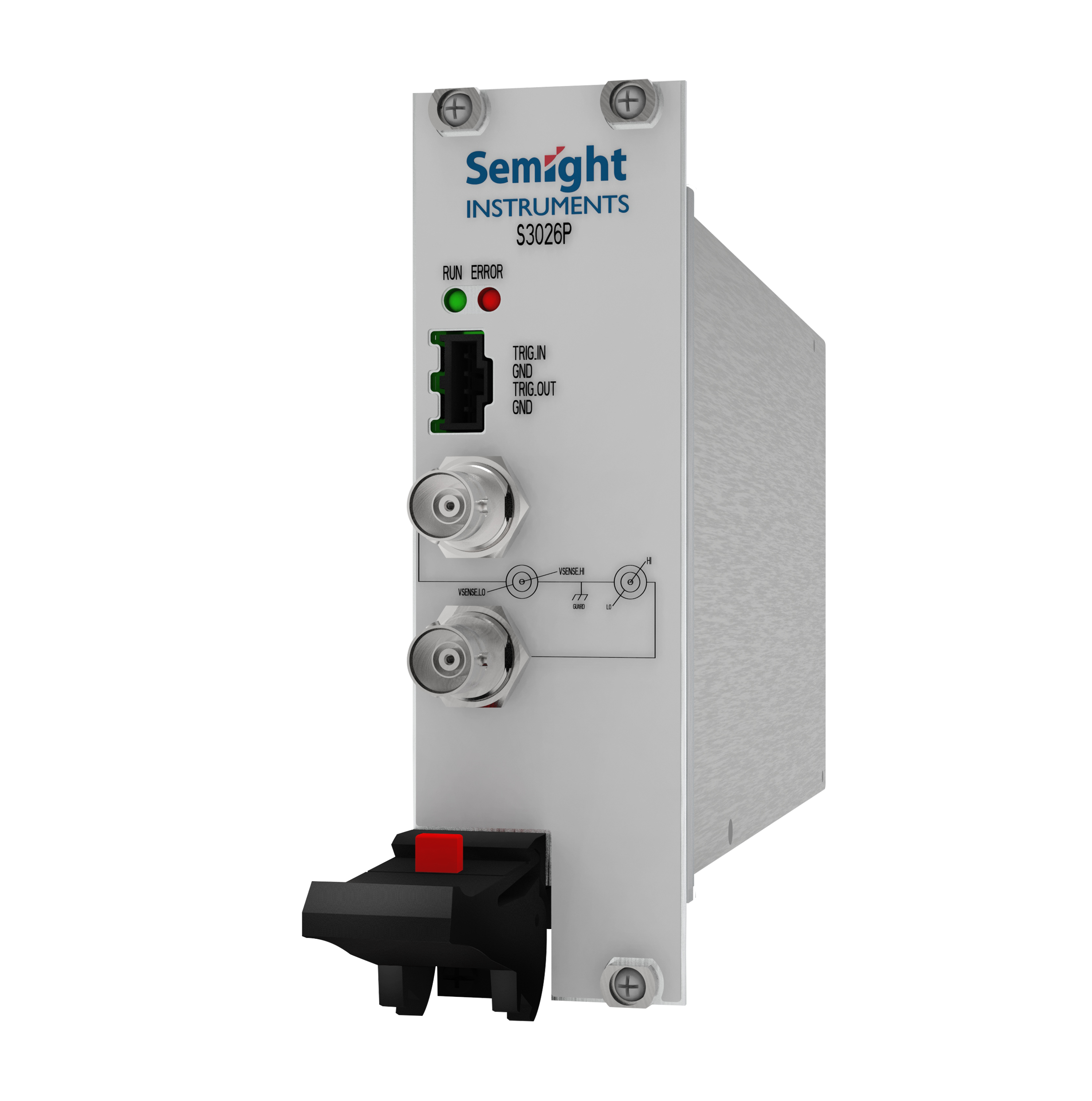
S3026P
Single channel PXIE pulse current source/measurement unit
Semight Instruments S3026P is a standard single channel pulse current source/measurement unit launched for the LiDAR market, supporting high-precision pulse current output and synchronous measurement of pulse current and DUT voltage drop.
Feature

Pulse width: minimum 1us, maximum 500us
Suitable for faster tested devices to better avoid the impact of temperature on test results
high-speed measurement
ADC up to 125MSA/S
large range
±1.5A;10V
Stronger load adaptability
Test loads with different characteristics to ensure that the waveform does not experience overshoot or other distortions
high speed synchronization
Multi channel and multi model collaborative measurement
Real time reading of DUT voltage drop for pulse current
No additional equipment required, precise monitoring of current testing conditions, real-time reading back of test resultsFunctions and advantages
Working conditions:
Temperature 23 ℃± 5 ℃
Relative humidity<70%
Temperature coefficient ± (0.15 × Accuracy index)/° C (0 ℃ -18 ℃, 28 ℃ -50 ℃)
Measure after preheating for 60 minutes, and the ambient temperature change during measurement is less than ± 3 ℃
Calibration cycle 1 year
The output is closed and the power interface is short circuited. At this time, the withstand current cannot exceed 50mA
Entering standby mode after over temperature protection
| Current accuracy | Range | Programming Resolution | Accuracy | Accuracy |
| ± (%RD+mA) | ± (%RD+mA) | |||
| (10us pulse width) | (1us pulse width) | |||
| ±150mA | 20uA | 0.1%+0.5mA | 1%+2mA | |
| ±750mA | 40uA | 0.1%+1mA | 1%+10mA | |
| ±1.5A | 100uA | 0.1%+2mA | 1%+20mA | |
| Current noise | Range | Typical Noise (resistive load, RMS) | Typical Noise (resistive load, RMS) | Typical Noise (resistive load, RMS) |
| 10k-20MHz | 10k-10MHz | 10k-1MHz | ||
| ±150mA | 1mA | 0.8mA | 0.5mA | |
| ±750mA | 3mA | 2.5mA | 1.4mA | |
| ±1.5A | 5mA | 4mA | 2.4mA | |
| Maximum load voltage | 10V |
1. Output electrical short; 2. Total cable and DUT inductance < 200nH (100k); 3. Pulse width measurement from rising edge 10% to falling edge 90% |
||
| Pulse width | 80ns | |||
| Programming | ||||
| Resolution | ||||
| Maximum pulse width Ton-max | 500us | |||
| Minimum pulse width Ton-min | 1us | |||
| Pulse minimum turn-off time Toff-min | 500us | |||
| Pulse width accuracy | 100ns | |||
| Pulse width jitter | 80ns (typical value) | |||
| Pulse-period jitter | 500ns (typical value) | |||
| Rise time (10%-90%) | <200ns | |||
| Pulse overshoot | <0.5% | |||
| Current regulation | linear | 0.05% of the range | ||
| load | ±100uA | |||
| Duty cycle | D<3-|Ibias|/[(Vsp-Vload)*(|Iset|-|Ibias|)] | |||
| Iset: programing current; | ||||
| D: duty cycle; | ||||
| Vsp: source protection voltage; | ||||
| Vload: load voltage | ||||
| Maximum number of pulses per scan | 64k | |||
| PULSE | Range | Display resolution | Accuracy± (%RD+mV) | Accuracy± (%RD+mV) | Sample rate | Test condition |
| voltage | (10us pulse width) | (1us pulse width) | ||||
| measure | ||||||
| 6V | 0.1mV | 0.1%+6mV | 0.2%+20mV | 10MSa/s | 1. The sampling rate is the maximum that can be used by the user; | |
| 2. The pulse width condition of the accuracy index refers to the time required from the start of measurement to stability to the accuracy requirements | ||||||
| 10V | 0.1%+10mV | 0.2%+30mV | ||||
| PULSE | Range | Display resolution | Accuracy± (%RD+mA) | Accuracy± (%RD+mA) | Sample rate | |
| Electric current | (under 10us pulse width) | (under 1us pulse width) | ||||
| measure | ||||||
| 150mA | 20uA | 0.1%+0.5mA | 0.2%+1mA | 10Msa/s | ||
| 750mA | 40uA | 0.1%+1mA | 0.2%+2.4mA | |||
| 1.5A | 100uA | 0.1%+2mA | 0.2%+5mA | |||
| Remote Voltage Sense | The maximum voltage between HI and SENSE HI =±10v; | |||||
| (PULSE voltage measurement) | The maximum voltage between LO and SENSE LO =±10v; | |||||
| Voltage Source (DC) | Range | Programing resolution | Accuracy± (%RD+mV) |
Ripple (Vp-p) 10k-20MHz |
Maximum current output |
| ±10V | 1mV | 0.1%+10mV | <10mV | 10mA | |
| Current Measurement (DC) | Range | Display resolution | Accuracy± (%RD+nA) | Sample rate | Normal sampling rate |
| 100uA | 10nA | 0.1%+100nA | 10Msa/s | 10NPLC | |
| 100nA | 10pA | 0.1%+0.1nA | |||
| Voltage Measurement (DC) | Range | Display resolution | Precision | Sample rate | |
| ± (%RD+mV) | |||||
| ±10V | 1mV | 0.1%+10mV | 10Msa/s | ||
|
Remote Voltage Sense (When measuring DC voltage) |
The maximum voltage between HI and SENSE HI =±1v; The maximum voltage between LO and SENSE LO =±1v; |
||||
| Current accuracy | Range | Programing resolution | Accuracy | Accuracy |
| ± (%RD+mA) | ± (%RD+mA) | |||
| (10us pulse width) | (1us pulse width) | |||
| ±50mA | 20uA | 0.1%+0.5mA | 1%+2mA | |
| Current noise | Range | Typical Noise (resistive load, RMS) | Typical Noise (resistive load, RMS) | Typical Noise (resistive load, RMS) |
| 10k-20MHz | 10k-10MHz | 10k-1MHz | ||
| ±50mA | 1mA | 0.8mA | 0.5mA |
| Trig_IN/OUT | Signal level | Delay | Trigging mode |
| 5V | 100ns | Rising edge |
Similar recommendation
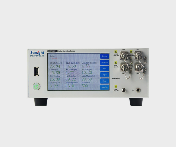
Optical communication network plays an important role in the rapid development of big data, cloud computing, 5G communication and other markets.
Semight Instruments offers various of instruments for optical Transceiver/Component testing, including wide bandwidth sampling oscilloscope, NRZ/PAM4 bit error ratio tester , burst error ratio tester, fast wavelength meter, optical spectrum analyzer, high precise source measure unit, 400G network analyzer ,optical power meter, optical attenuator, optical switch etc. Provide cost-effective complete solutions.
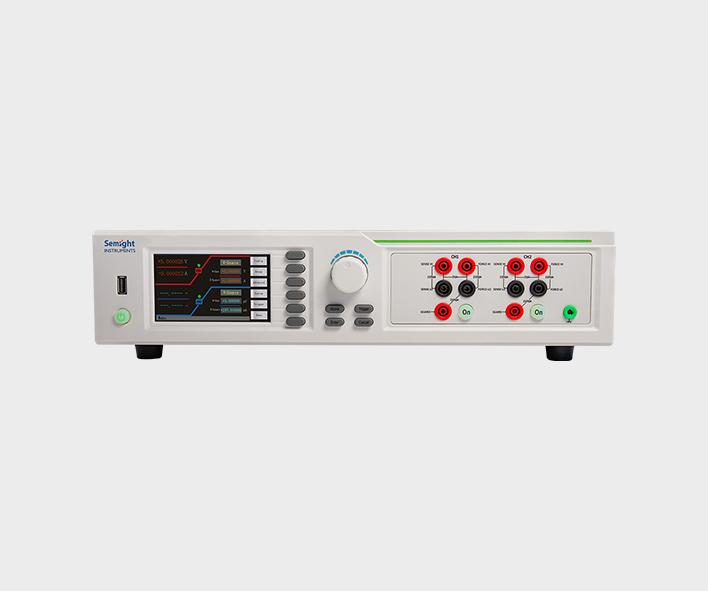
The high-precision source meter integrates the functions of voltage source, current source, voltmeter, ampere meter, and electronic load in one, which is widely used in high-precision IV test and measurement for various discrete components, photovoltaic, new energy, battery and other industries. Semight Instrument provides high-precision benchtop source meters and plug-in PXIe source meter modules of standard PXIe chassis, fully meeting the application of various test scenarios.
Details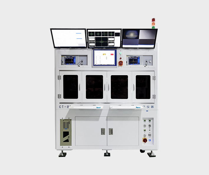
Burn-in testing of laser is an important method to ensure the reliability of laser. Through the test of COC or bare die, the early failure of laser caused by the defects in the process of laser production can be screened out in advance. Semight Instrument provides a complete solution from bare die to COC, from high temperature(150℃ or higher) to low temperature (-40℃), with CoC automatic loading and unloading system, forming a complete test solution, Semight Instrument's laser chip burn-in/load/unload test system has been widely recognized by the market.
Details
The semiconductor front-end test is mainly used in the wafer processing to check whether the processing parameters of the wafer products meet the design requirements or there are defects affecting the yield after each step of the manufacturing process. The semiconductor back-end test equipment is mainly used after wafer processing to check whether the performance of the chip meets the requirements, which belongs to the electrical performance test. Semight Instrument provide integrated solutions such as wafer burn in and known good die tester, improve test efficiency and reduce test cost.
Detailsmailbox
Service hotline
follow
full name
e-mail address
Email verification code
Telephone
password
Confirm Password
e-mail address
Email verification code
New Password
Confirm Password
 Datasheet
 Apply for prototype